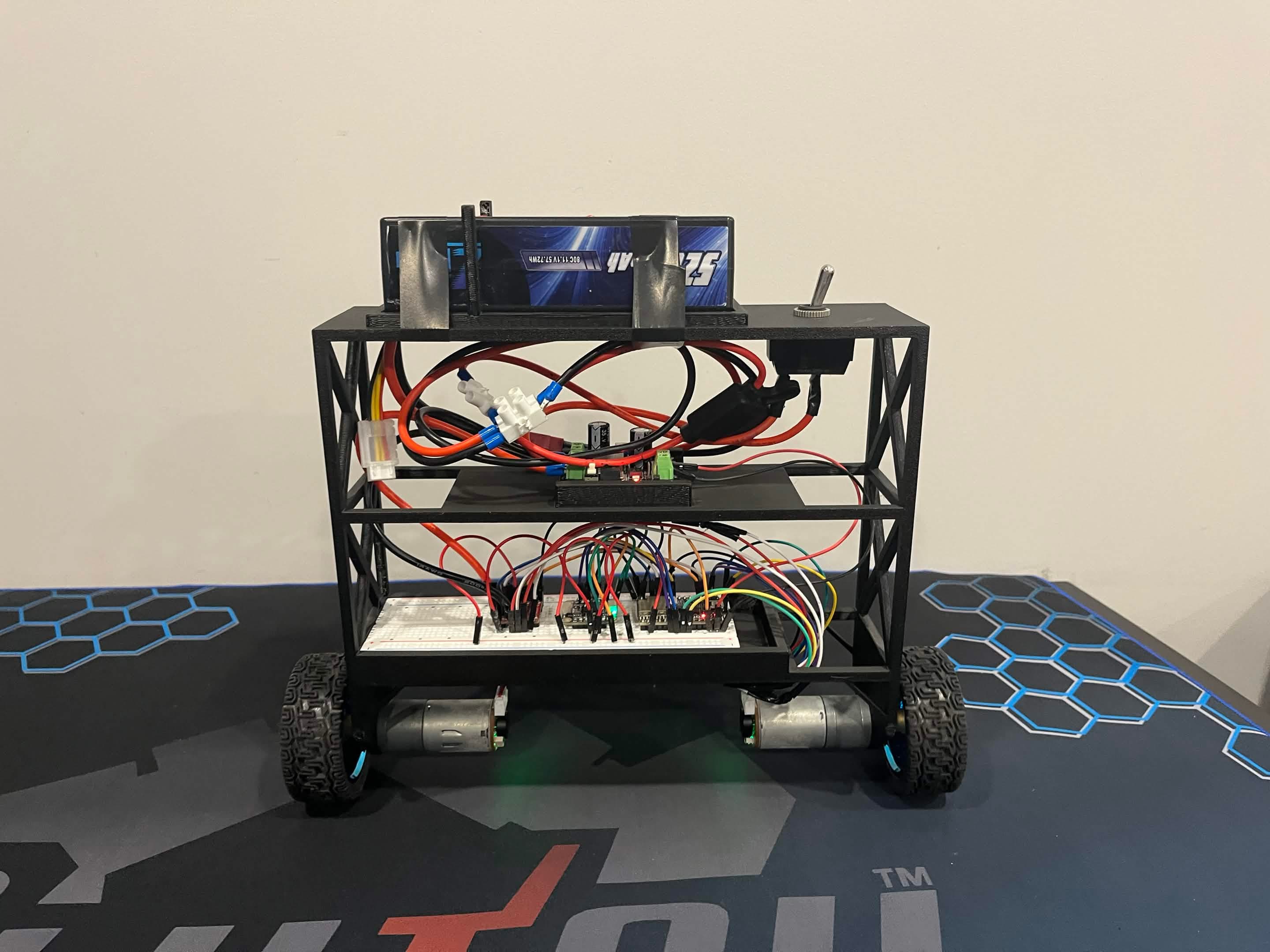
Overview
Angus started as a way to learn the whole robotics stack at once: mechanical design, power electronics, sensors, embedded C++, motor control, and feedback control.
Keeping a two-wheel robot upright forces every subsystem to work together. The sensor estimate has to be trustworthy, the motors have to respond quickly, the chassis has to behave predictably, and the controller has to react before the robot falls outside its recoverable range.
Story to emphasize
System architecture
The ESP32-C3 reads orientation from the BNO085, computes the balance correction, and drives two DC motors through the motor driver. Encoder feedback gives the platform a path toward velocity and position control.
| Component | Value |
|---|---|
| Controller | ESP32-C3 |
| IMU | BNO085 |
| Motor driver | TB6612FNG |
| Drive | 2 x 12 V DC motors + encoders |
| Battery | 3S LiPo, 11.1 V |
| Control | PID balance loop |
Battery to regulator to controller and IMU to motor driver to motors. A simple diagram is enough.
Build process
- Make the motors reliable first. Verify direction, PWM response, encoder wiring, and power delivery before trying to balance.
- Get stable orientation data. Integrate the IMU and confirm the software axis matches the robot's physical forward/backward tilt.
- Close the feedback loop. Turn tilt error into a signed motor command and add fall protection / integral reset logic.
- Tune on the real chassis. Increase response until it catches itself, then add damping and correction while watching for saturation.
Control loop
The interesting part of PID is not the equation itself but how each gain appears physically. Too little proportional gain and Angus cannot catch itself; too much produces rapid oscillation. Integral can correct a persistent lean but can also wind up after a fall, while derivative action helps damp motion but is sensitive to noise.
A remaining issue is forward drift: angle control can keep the chassis upright without keeping wheel velocity at zero.
error = target_angle - roll;
integral += error * dt;
derivative = (error - previous_error) / dt;
command = Kp*error + Ki*integral + Kd*derivative;
if (abs(roll) > 45deg) {
integral = 0;
motors.stop();
}Figure 2 - Simplified balance-controller structure.
Observed issue
Forward drift
Upright does not necessarily mean stationary; the robot can balance while slowly moving away.
Next control layer
Velocity outer loop
Use encoder velocity to shift the balance setpoint and pull the robot back toward zero speed.
Iterations
Testing made it clear that "bad PID" can actually be a mechanical, electrical, or sensor problem. Chassis flex, wheel alignment, motor mismatch, axis conventions, and battery behavior all change the plant being controlled.
A strong case study should show at least one failed version and explain what that failure taught you.
Place an early Angus build beside the current one and caption the mechanical or wiring changes.
Results & lessons
The project produced a working platform that ties together embedded software, sensing, motor driving, encoders, power distribution, and real-time feedback control.
- Controls: each gain became easier to understand when tied to a visible physical behavior.
- Embedded: predictable timing and clean sensor data matter as much as the controller equation.
- Mechanical: stiffness, centre of mass, friction, and wheel alignment directly affect control.
- Debugging: isolate one subsystem at a time before changing gains.
Next steps
The next version would add an encoder-based velocity/position loop, better telemetry for tuning, and a more systematic comparison between PID and state-space control such as LQR. I would also redesign the chassis around easier battery access and more repeatable component mounting.
Best final assets